|
CCS ICD-U40 Update from V1 to V5C |
|||||
 |
Instructions to
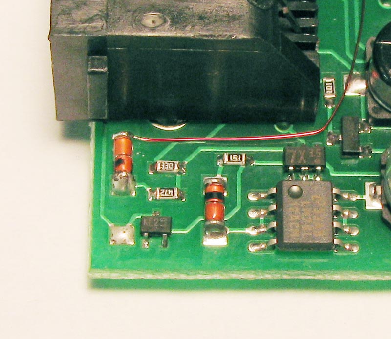
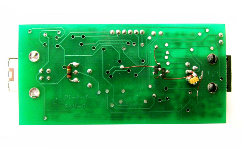
update V1 to V5C V1 Schematic/Assembly V5 Schematic/Assembly If you have some old ICD-U40s lying around that don't quite work with the latest version of CCS PICC, here is the instructions to update your hardware along with the schematics of both versions. Just follow the steps from A to N, reflash the PIC and you're ready to go! The board version is printed in copper on the component side next to the USB connector. The V1 unit used a simple pull up scheme to connect to low voltage targets (<5V of the VBus). The V5 unit incorporated a clock driver for the PGMCLK signal and I2C style open drain bidirectional buffers for the PGMDAT and LVP signals. The Vpp voltage sense has been moved to the output of the boost regulator instead of the target Vpp pin. The target Vdd sense has been pulled off of the Vbus rail and moved to the target connector as well as the Vdd pull-up via CR5. A 1M feedback resistor has also been added across the USB controller resonator. |
||||
| ICD-U40 2.62 Hex | PIC18F252 ROM image to reflash into V1 processor to upgrade it to V5C | ||||
|
ICD-U40 2.62 EE Listing |
If your ICD connects in the debugger but you get an error message like "Can't connect, programmer is already connected to another program..." or the CCSLOAD boots and then exits immediately then you probably have a blank EEPROM connected to the FT232BM. In the windows device manager you will also see the ICD listed in the com-ports instead of the USB devices as an "ICD-U40" where it should be. If this is the case, program in the 93LC46B (U4) image. | ||||
|
|||||