|
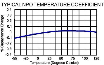
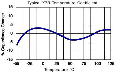
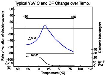
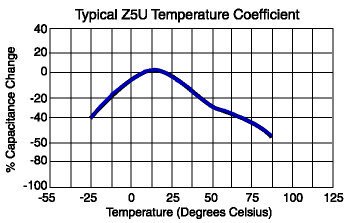
TCC Temperature Coefficient of Capacitance For common ceramic capacitor dielectrics |
|||||
| Low Limit - DegC | High Limit - DegC | Maximum Allowable Capacitance Change From +25°C (@ 0 VDC) % | |||
| X | -55 | 2 | +45 | A | +/- 1 |
| Y | -30 | 4 | +65 | B | +/- 1.5 |
| Z | +10 | 5 | +85 | C | +/- 2.2 |
| 6 | +105 | D | +/- 3.3 | ||
| 7 | +125 | E | +/- 4.7 | ||
| 8 | +150 | F | +/- 7.5 | ||
| L | +/-15 (-55-125C) +15/-40 (125-150C) |
||||
| P | +/- 10 | ||||
| R | +/- 15 | ||||
| S | +/- 20 | ||||
| T | +22 / -33 | ||||
| U | +22 / -56 | ||||
| V | +22 / -82 | ||||
| X7R example: This capacitor has an operating temperature from -55 to +125 DegC and a change in capacitance of no more than +/- 15% from its initial value over that operating range. Note that Tolerance is a percentage variation from the initial value indicated on the box, typically specified at 25C. The tempco is then a change from this actual starting point as the temperature changes. | |||||
    |
|||||