Circuits - TES
TES Public Domain Designs (
Non-TES
)
Switcher Efficiency
Sweeper
1KW Isolated
Resistance Heater and
Brazing Stand
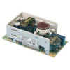
Condor GPC41-5
180V/40W Conversion
HBridge Stress Tester
7441 / 74141
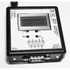
Nixie Driver Tester
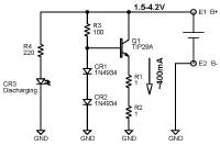
CC Discharger
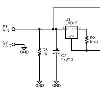
CCCV Charger
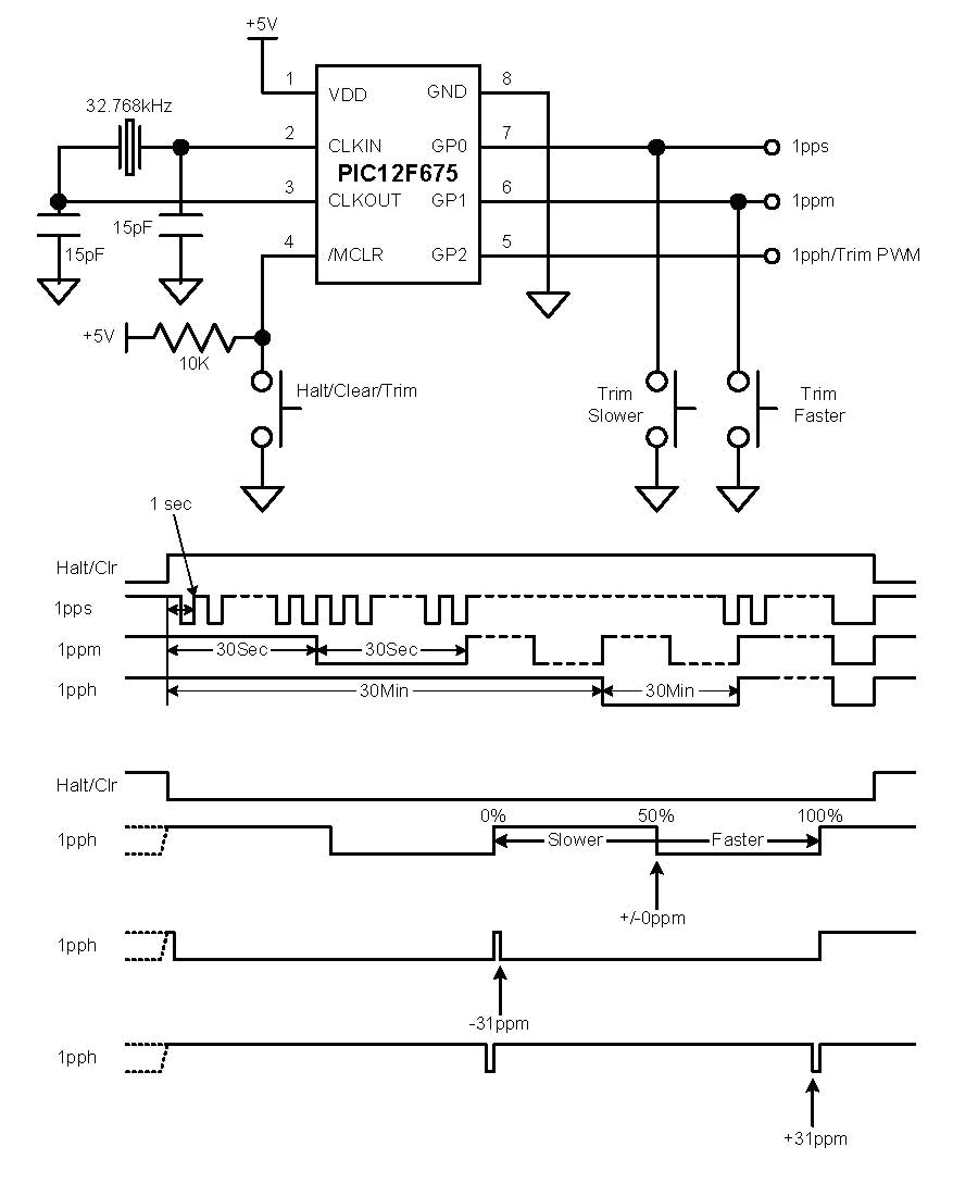
PIC Clock Divider-II
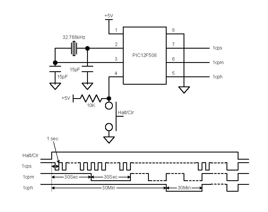
PIC Clock Divider-I
Line Ripple Clock
Conditioning
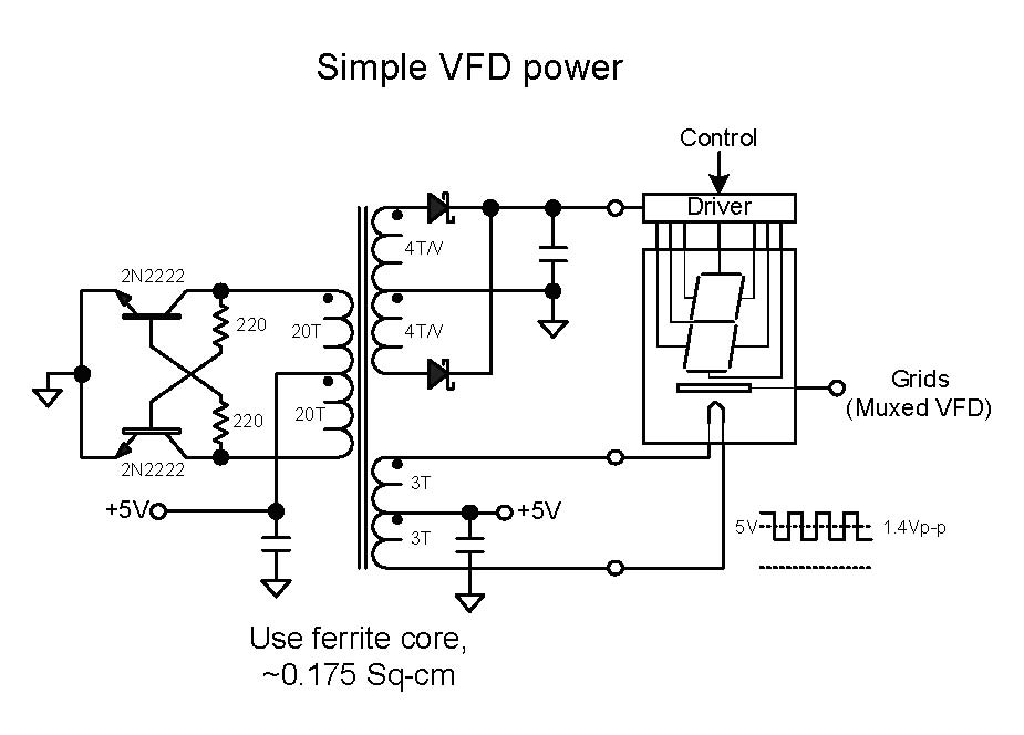
Simple VFD Power
HP34401 Data Logger
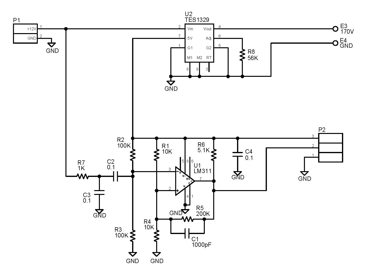
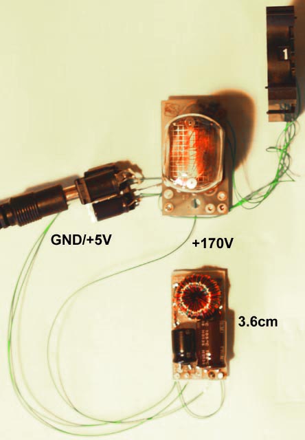
Simple Nixie HVPS-II
Simple Nixie HVPS-I
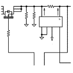
AC Current Detect Relay
Spot Welder
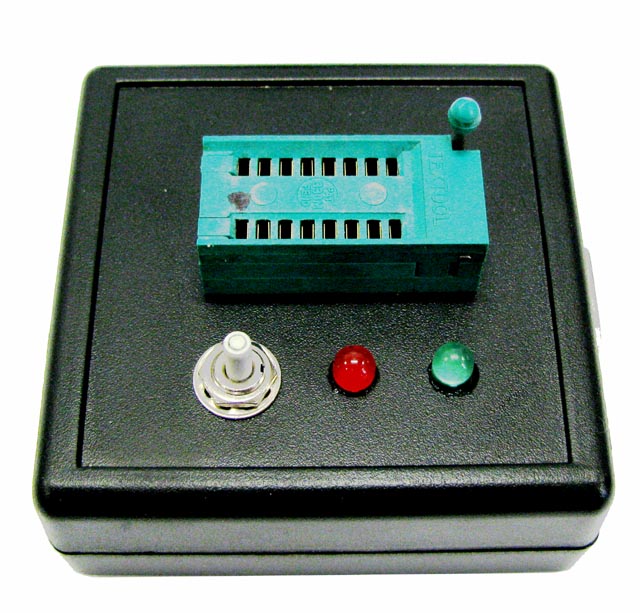
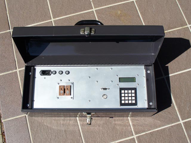
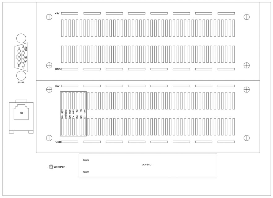
PIC Breadboard Box
74595 SIPO Connection
Any questions or comments?
This page last updated on August 28, 2011